I have been playing around in Autodesk Inventor, and I have finally leared how to perform Static and Dynamic Stress Analysis of parts. This is a very powerful feature, and basically determines the structural limits of a material, given it's construction and materials.
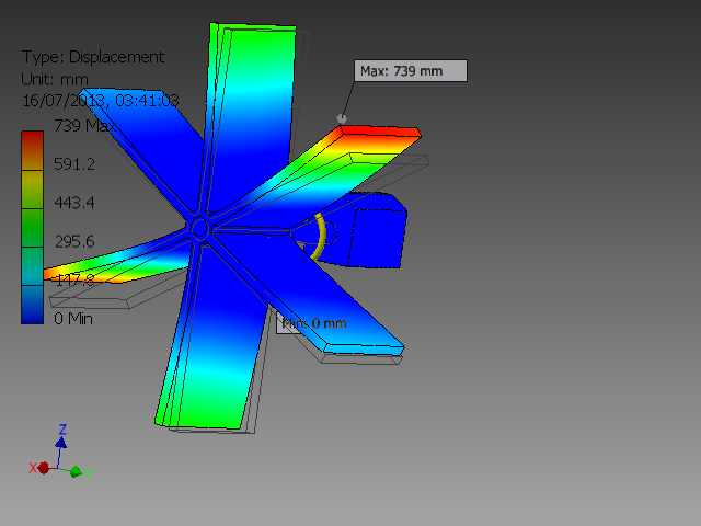
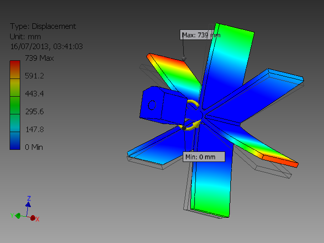
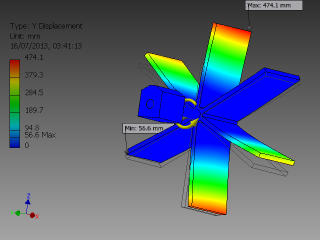
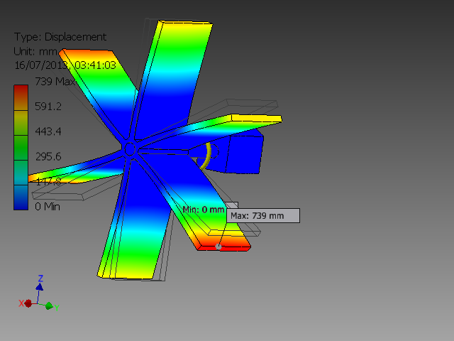
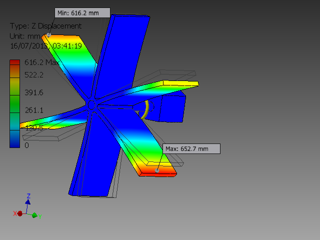
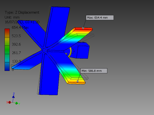
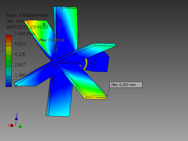
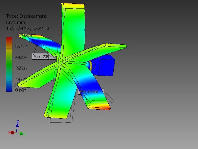
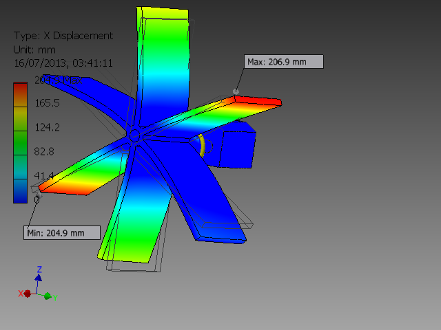
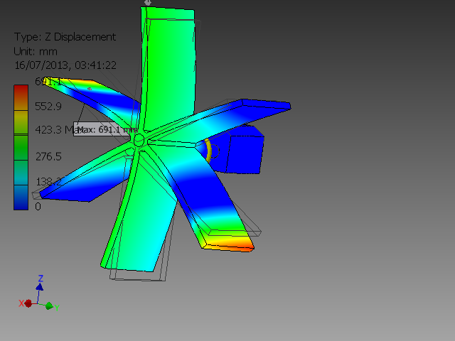
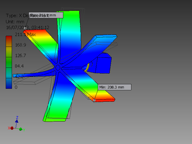
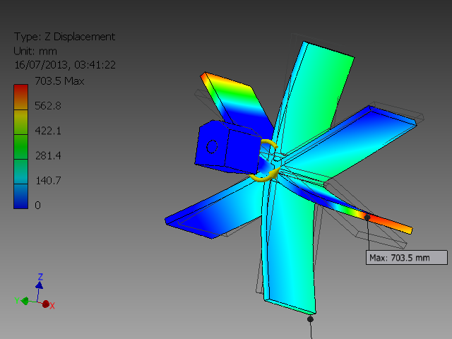
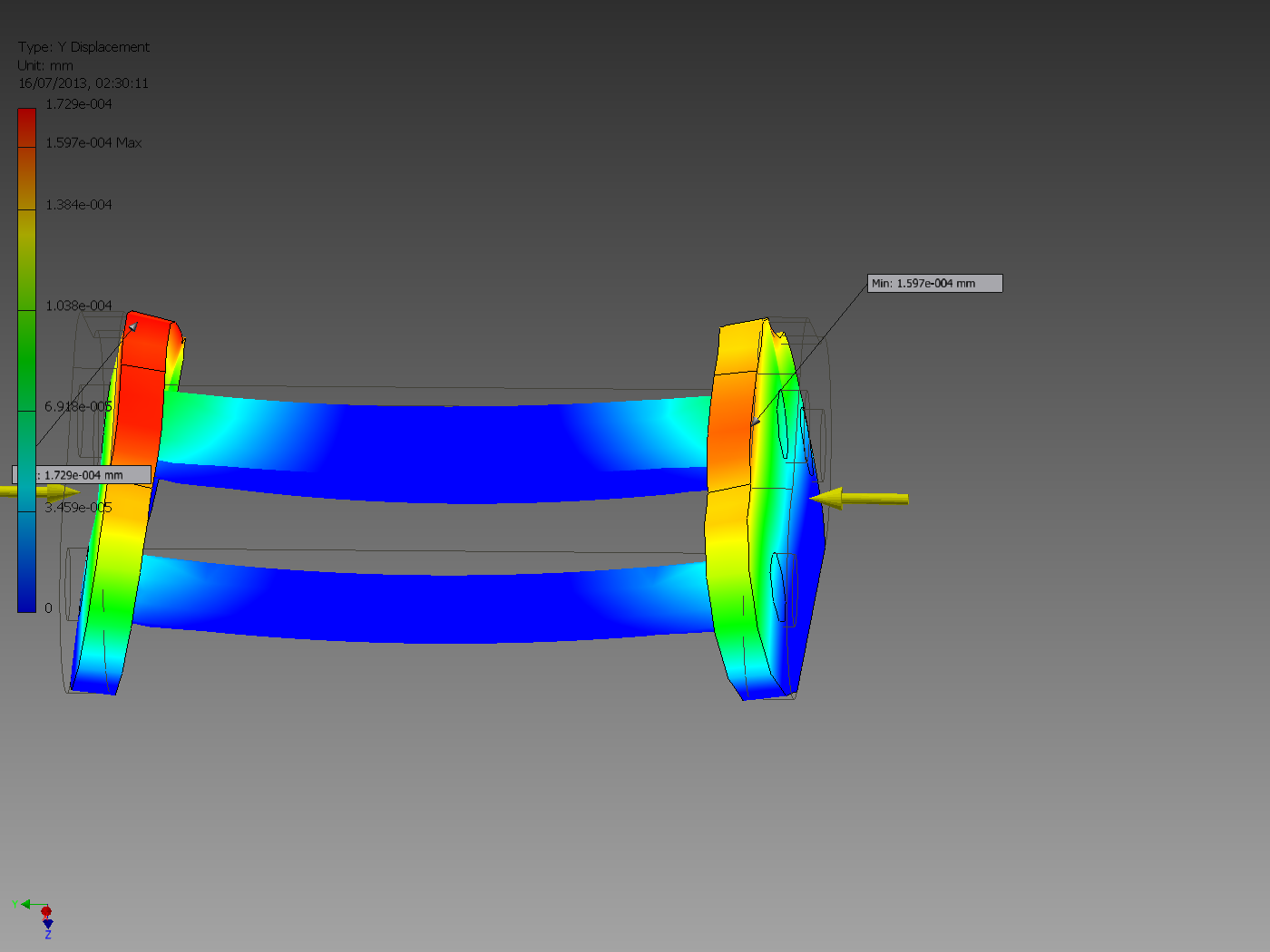
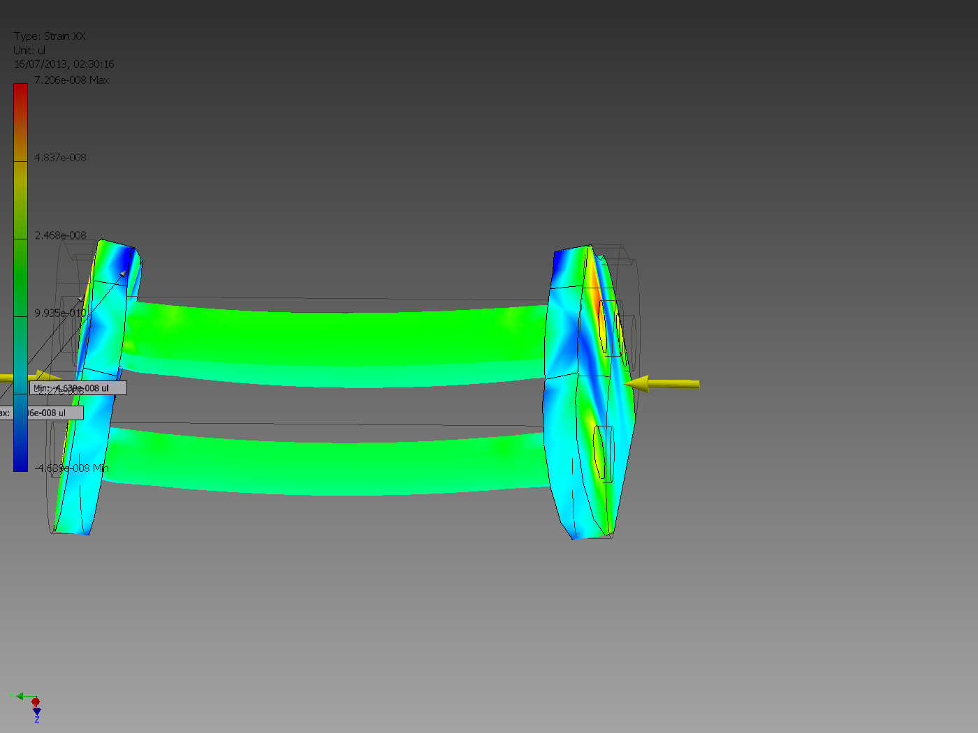
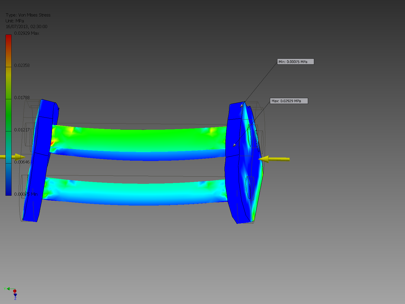
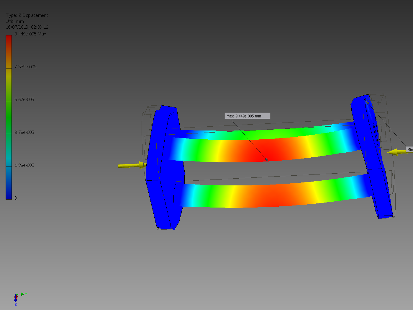
I have created two models to test this: The first is a dynamic model. It is a simple paddle-wheel connected to a housing (containing a motor, to generate HEP) via a rotating shaft. The housing and the shaft are constructed from stainless steel, and the the paddles are constructed from aluminium. I have simulated a load of 1000 Newtons per mm on the shaft. The images below are from the report generated by the program, the colours increase in intensity as the stresses increase. Blue means no strain, while red means maximum strain. The grey outline is the original assembly, before the simulation has been run. It can be clearly seen here that the aluminium paddles are deforming and bending with the strain imposed, and would likely fail quickly if the assembly was to be constructed in this manner.
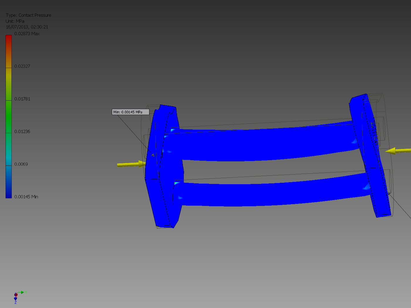
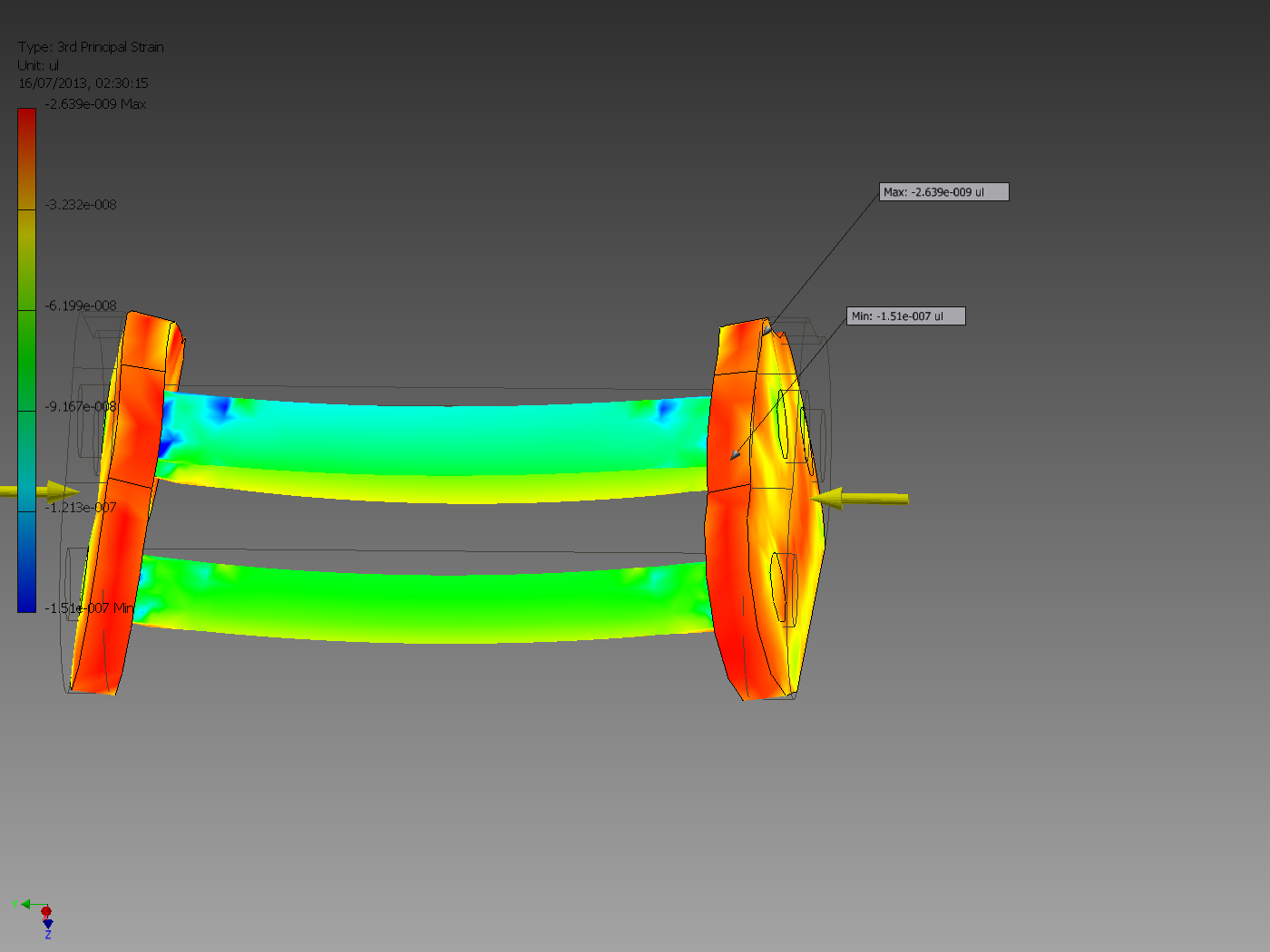
The second model is a simple bracket assembly: Two steel plates connected to the floor, and connected together with steel rods. This simulation simulates a load of 1000 N being appled to each of the plates from the side, essentially compressing the assembly. The steel connecting rods and the floor mountings are therefore resisting the load. It can be clearly seen from the simulation that they are not capable of resisting this much force, and are buckling. The simulation shows the structure slowly failing, with weak spots forming and then progressing through the assembly. It seems that the main point of failure is the steel rod on top of the assembly, above the other two. Since this is by itself, it receives disproportionate load compared to the other two, and fails first. When it fails the two rods beneath it are subject to additional strain, and they beging to fail, and finally the floor mountings begin to fail. Based on the results of this simulation, adding another steel rod beside the first one, creating a square as opposed to a triangular structure, would be the best way to reinforce this structure, since it would mean the force would be distributed equally among all connecting rods.
I have also created a short animation of the Stress Analysis Simulation for the Turbine model: