I realised that I needed a reliable power supply for my robot after I accidentally burned out a small camera I was trying to wire up for it.
I designed the circuit myself, using two L7812 12V voltage regulators. These produce a clean, steady, 12V output from a variable voltage input, and supply a maximum of 1.5 Amps. This is very useful when using batteries, since a 12V battery will not produce a constant 12V, it will vary from 13V or over to less than 12V as the battery discharges.
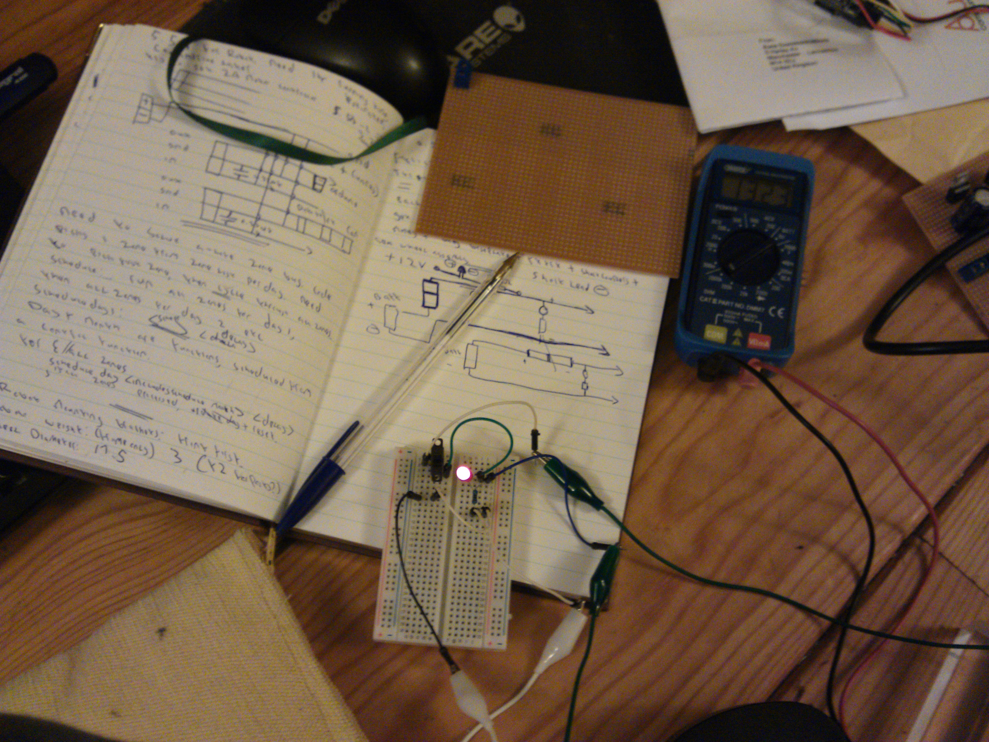
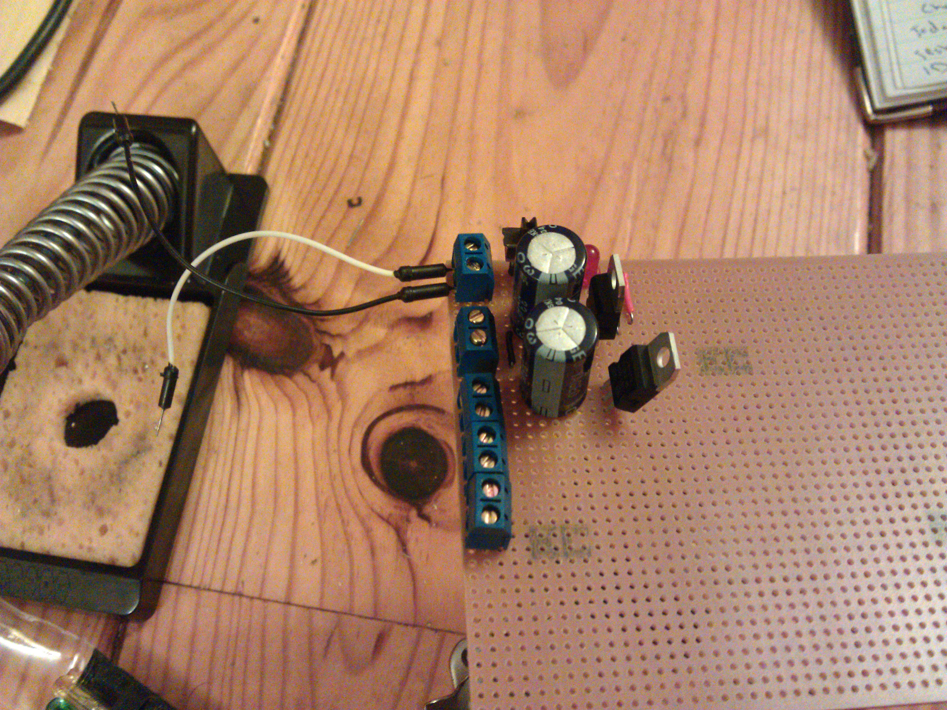
The two large capacitors are for smoothing the output voltage even further, I tested them with a multimeter, and the output is much closer to the ideal 12V with the caps connected. I could have added two smaller capacitors to further smooth the current, but I didn't feel the need to, it was working very well even without them.
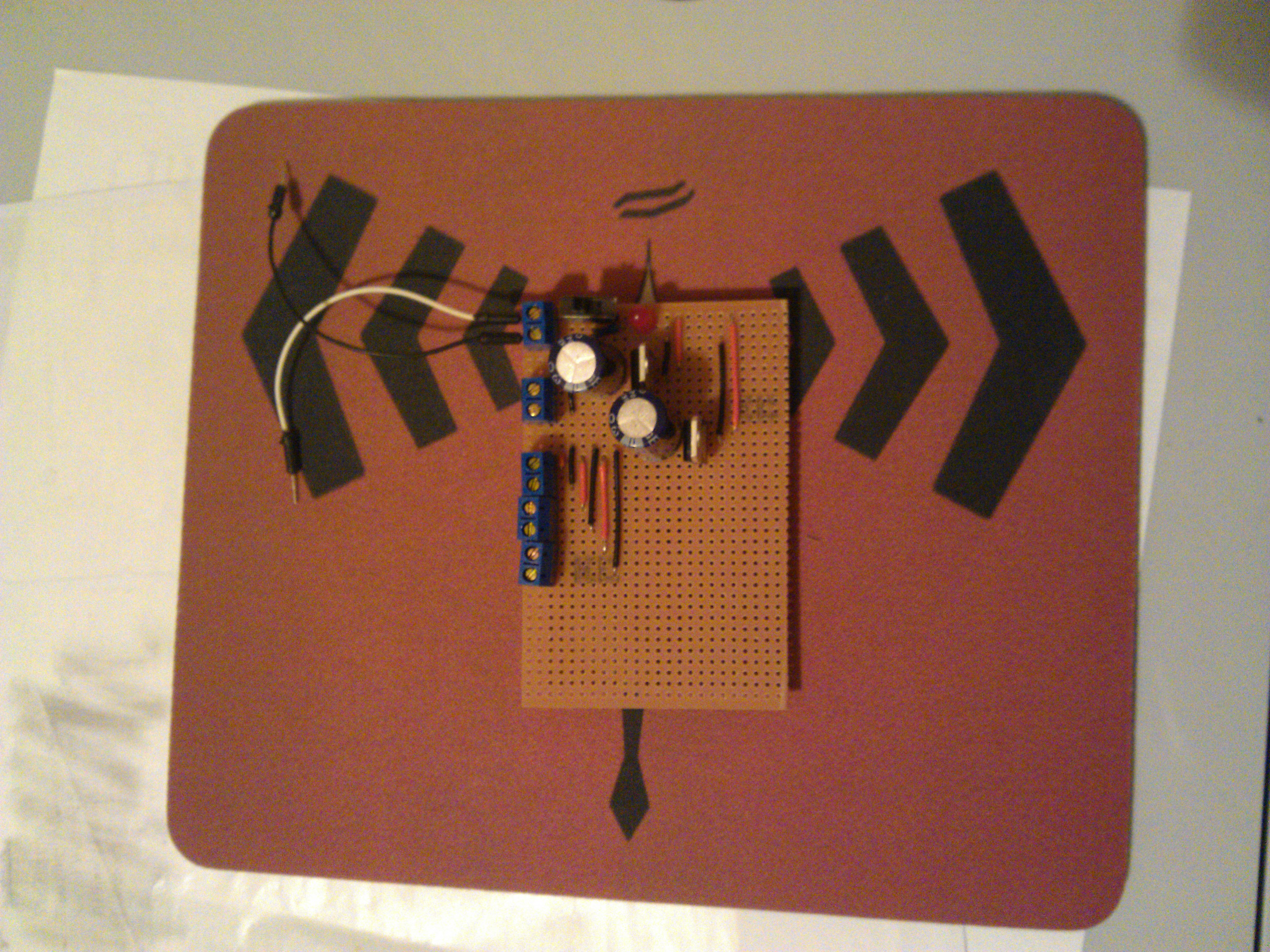
I connected five screw terminals to the side of the board. These are simple, inexpensive components that have a screw on top, and a hole through the middle. You can insert a wire into the hole, and tighten the screw, to create a relatively secure connection which can easily be disconnected later if required. This allows me to mix and match components, or reuse the voltage regulator for other projects, which I couldn't do if I had soldered the wires in.
The first screw terminal is for the power input, and has a switch and a power indicating LED.
The next four screw terminals are for the 12V output. The first terminal is connected directly to one of the voltage regulators, and can therefore provide the full 1.5A that the regulator allows. I will probably use it for the Microcontroller, which could draw up to 800 mA.
The next three terminals share the same L7812, meaning they share the 1.5A current between them. I will use these for lower voltage components, such as the Video Transmitter, Data Receiver, and the Camera, all of which draw very little current.
The motors and motor controller for this robot will draw a lot of current, I will need a 4A or posibly even an 8A motor controller for them, so it will be connected directly to the battery.
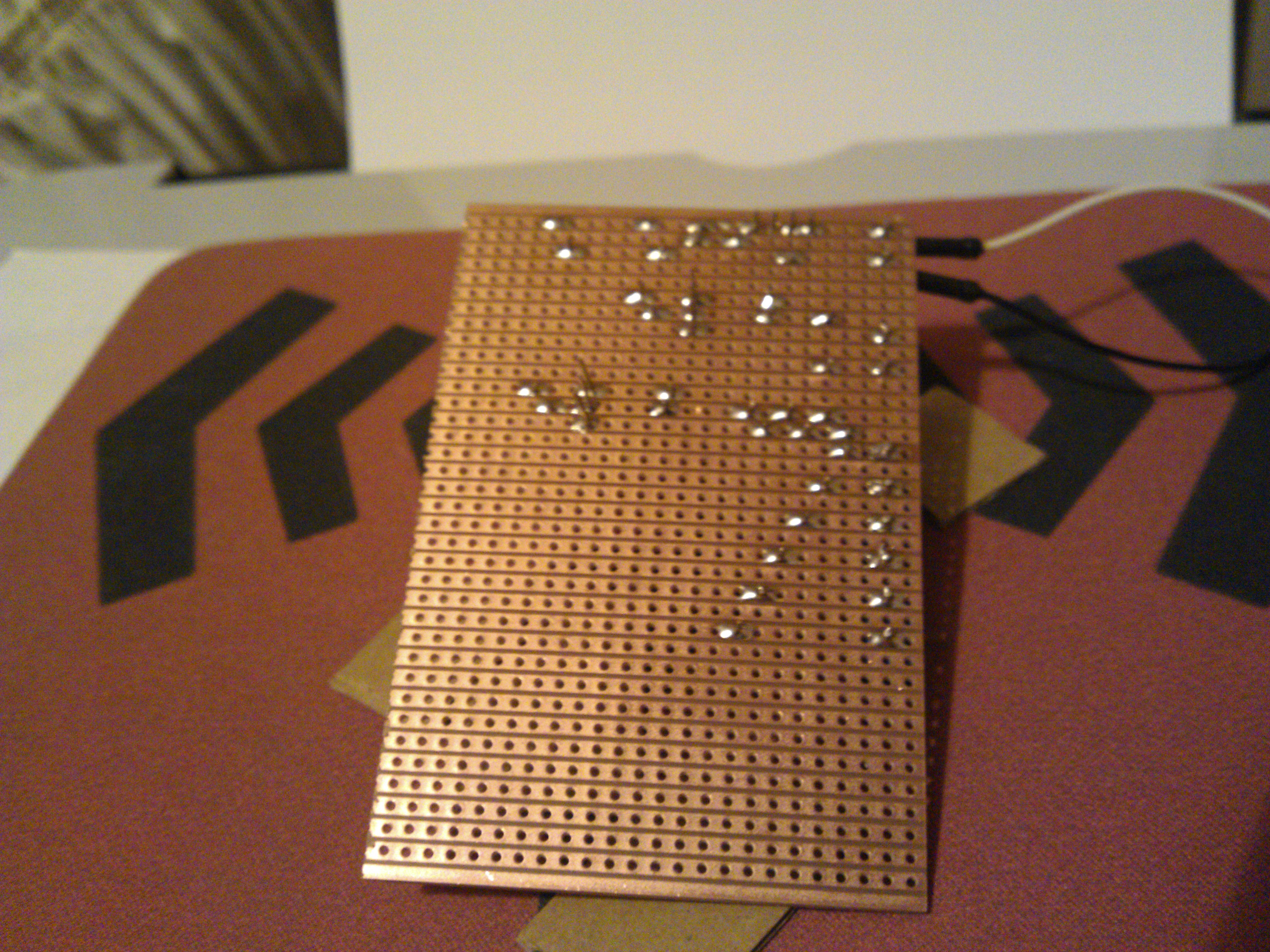
I have also left enough space at the bottom of the board to add two more rails for more terminals and regulators if I need them later.
I haven't included any reverse polarity protection diodes, which I possibly should have, but I didn't have any and I didn't want to wait to order them, so I will just have to be careful not to connect the battery backwards.