
Thermal Imager: Progress Update 2
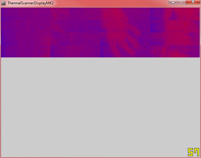
I have made some progress here. In additon to adding some support for colour coded heat images (although not full RGB colour) I have managed to stitch together several images to form one single image.
The images below show my early attempts at this. The image quality and resolution are low, but you should be able to make out my hand in the image fairly clearly. The next step is to further increase the resolution and quality of the combined image using averaging and blurring algorithms.
I’m still not sure how to do this yet, but I have some ideas.




March 3, 2014 @ 7:51 am
Looking good!
March 3, 2014 @ 8:30 pm
Thank you!
March 7, 2014 @ 9:52 am
Got the sensor working now. Find the datasheet really difficult to understand at times and it appears to be full of errors. Nevertheless i worked it out. Maybe you can answer a question i have:
When calculating alpha, the datasheet uses two different formulas. At the part where they explain how to calculate alpha one formula is used, but in the example they suddenly added something with the compensation pixel to the formula :S.
I still have to add the alpha calculation to the software (atm i use a constant XD). But which formula do you use?
March 8, 2014 @ 6:16 am
Ah, excellent! I had some issues with the wiring of the thermal sensor based on the datasheet, it was quite hard to read!
There is some excellent information and sample code (For Arduino only) on the following thread:
http://forum.arduino.cc/index.php?PHPSESSID=dclp372raddds4sf39gmbtgca7&topic=126244.0
On page two the following link is posted:
https://github.com/nseidle/MLX90620_Example/blob/master/MLX90620_alphaCalculator/MLX90620_alphaCalculator.ino
That calculates all of the alpha information that you need, and can be plugged into the sketch given on page one of the first link.
I don’t know what microcontroller you are using, but even if it’s not an Arduino, you should be able to rewrite that code easily. Good luck!
March 8, 2014 @ 11:21 am
Yeah I have been using that sample code as reference:P The second link you gave me is excellent! Got the alpha calculations in my program now, but it doesn’t hurt to test them with that code.
I am using an Arduino Mega. It seems that many people wire the MLX90620 through external electronics with diodes and stuff just to get to the desired 2.6V. However, I have seen people hook it straight up to the 3.3V. This is also how I hooked it up and it works great! A couple of pull-up resistors just to be safe (I know the Arduino has them built).
Right now I’m trying to figure out how to apply a thermal colorgradient over the pixels to make a real thermal image. But it certainly looks easier than it is:P
March 16, 2014 @ 12:33 am
I’m glad you got the Alpha calculations working! Thermopile seems to be quite easy to use!
Yes, I used some resistors to wire up the thermopile, and it works fine. I have seen people using level shifters as well, but it seems that it is not really neccessary.
Have you tried looking up “Heat Maps”, and looking for related code samples? What I have learned is that there is no “correct” way to apply a color gradient, since it is “false” colour, objects are not really red, or blue, so you can basically apply any sequence of colours that you want. I just assumed that dark red was the hottest temperature that the device can read, and solid blue was the coldest colour that it can read, and interpolated a range of values between the two. But you can do anything you want, initially, I just converted the temperature into a range between 0 and 255 and used that to control the “brightness” of a pixel. It was just a grayscale image, but it seemed to work fine.
March 18, 2014 @ 8:11 am
It’s a shame I can’t upload pictures here:P I got the color gradient thing worked out quite nicely. And I interpolated the image so it ‘looks’ more detailed (can’t create pixels that aren’t there:P).
One more thing though, is your TGC value equal to 0, just like mine? It’s hard to believe my sensor doesn’t need color gradient compensation. And because TGC = 0, the compensation pixel is calculated for nothing since it is multiplied with the TGC value (something times 0 still equals 0…). Any thoughts?
March 22, 2014 @ 11:14 pm
No, I don’t think you can upload pictures yourself through this, do you have it hosted anywhere? I have my own ideas for interpolation as well, I assume you increased the resolution of the image, and then filled in the “gaps” so to speak by averaging out the brightness values between the pixels? That’s something I will be doing as well shortly.
I’m not sure what you mean by TGC value, is that the ambient temperature value picked up by the thermal sensor?
Have you mounted your sensor on a pan and tilt servo system, or are you using it as is? I am having trouble forming a clean image by panning and tilting the servo, there are always streaks between the individual scan blocks. It would have been easier to use a single pixel thermopile for this, but it would have been much slower.
March 24, 2014 @ 11:06 am
That’s precisely what I have done to my image. I used a formula for bilinear interpolation which is used if 4 points are known values. I just interpolated between these four pixels and the result is amazing. Somehow you can make out more detail while there really isn’t any extra information!
TGC is the thermal gradient compensation. It is explained in chapter 7.3.3.1 under number 2. This value is stored in the EEPROM of the sensor. However, mine equals 0… Thus all the calculations done with this value equals 0. Which means a lot of calibration calculations are left out in my case.
Currently I’m using the sensor as is. Originally I was planning on mounting it on a servo system like you. However, I’m now planning to move the sensor on a xy-plane and take images downwards. I have not yet implemented this as I just received the frameworks today. As soon as I got something I’ll let you know.