This is the voltage divider circuit that I build to solve my problem with accessing the SD card using the Atmel Chip.
The original circuit diagram was found here, on this thread on the Arduino forums.
The diagram is:

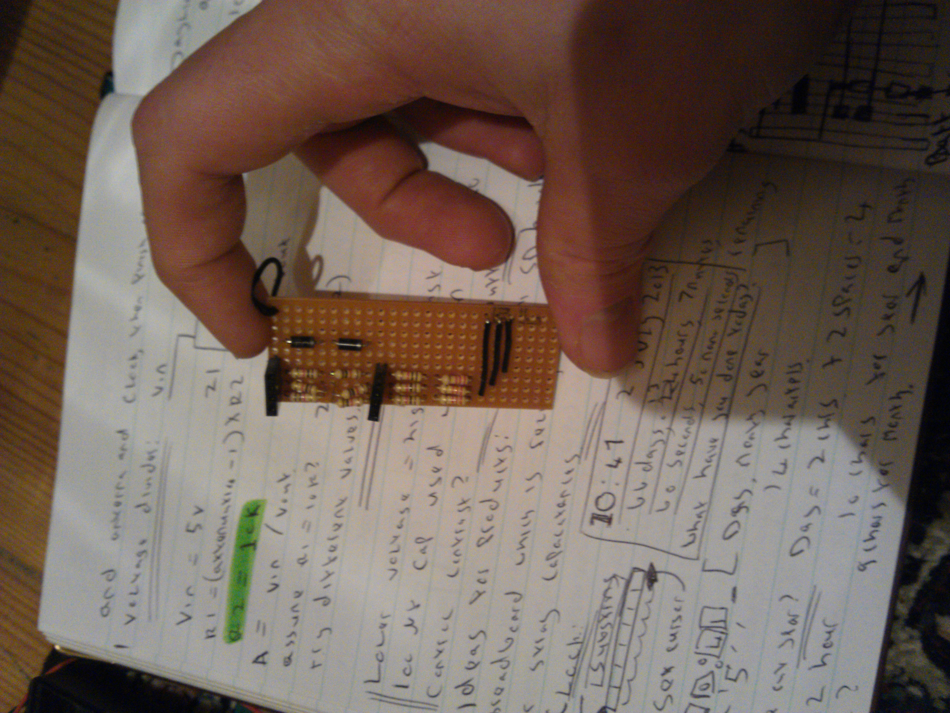
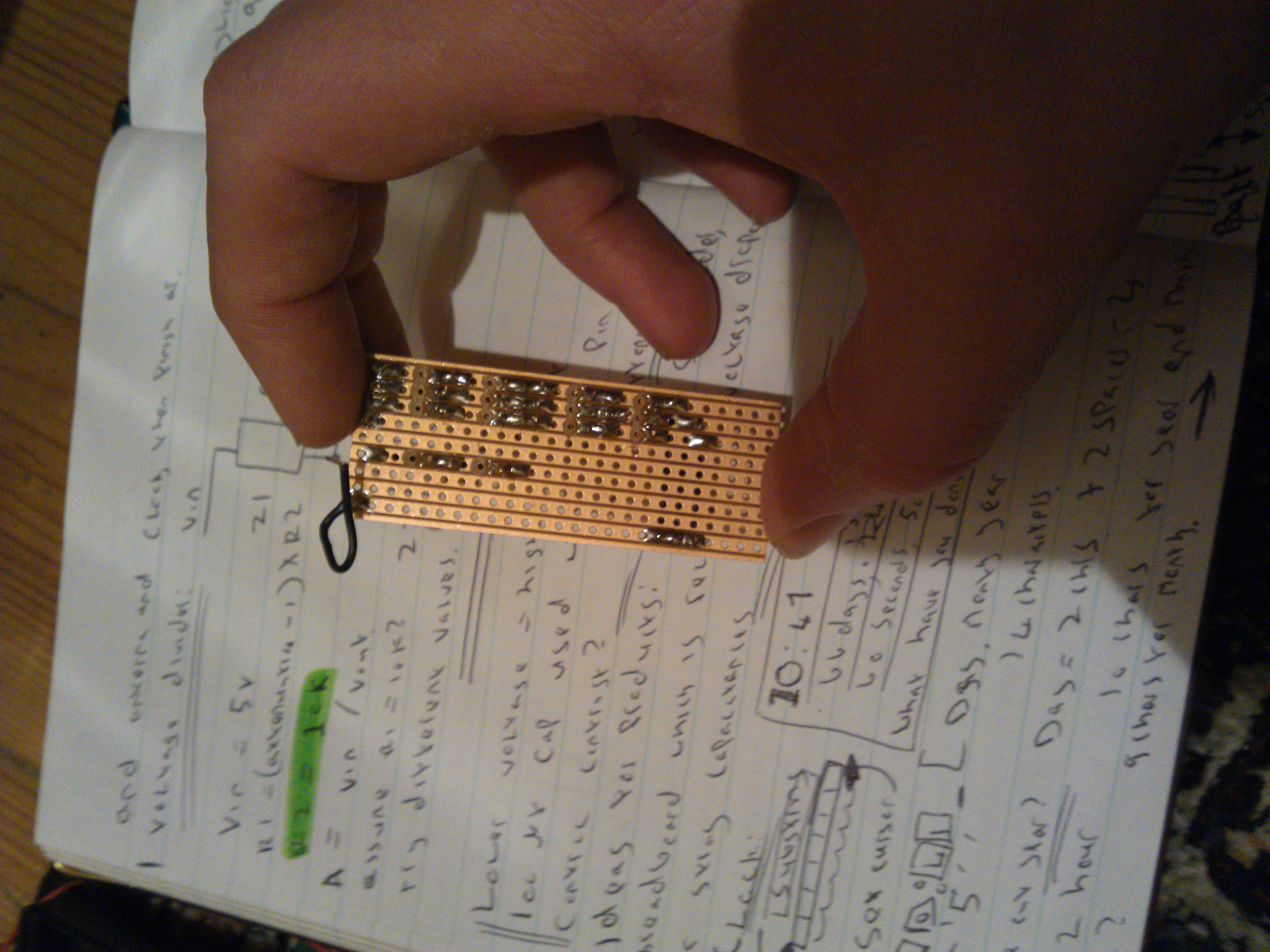
I didn't have any 1.8k or 3.3k resistors, and I didn't have time to order any, so I used 2 1k resistors to make 2k, and a 1k and a 2.2k to make 3.2k, which is close enough to work.
I also added some diodes to drop the voltage on the SD cards power pin from 5v to about 3.6v when under load. Resistor dividers aren't supposed to be used for powering devices, according to what I've read, only for data signals.
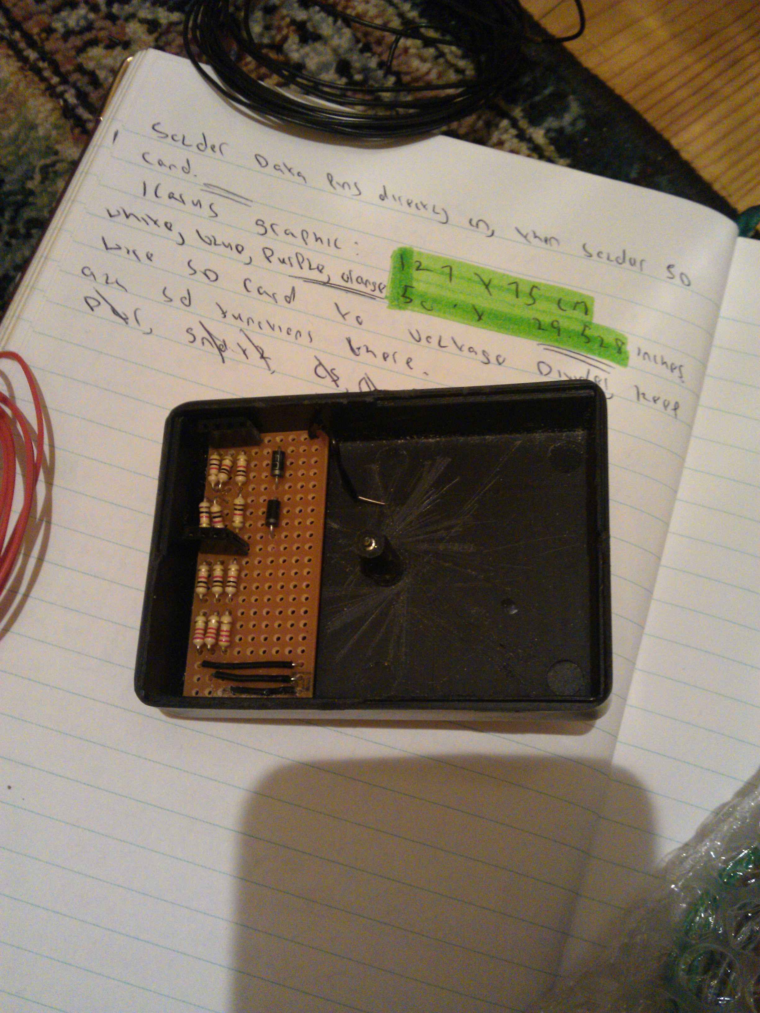
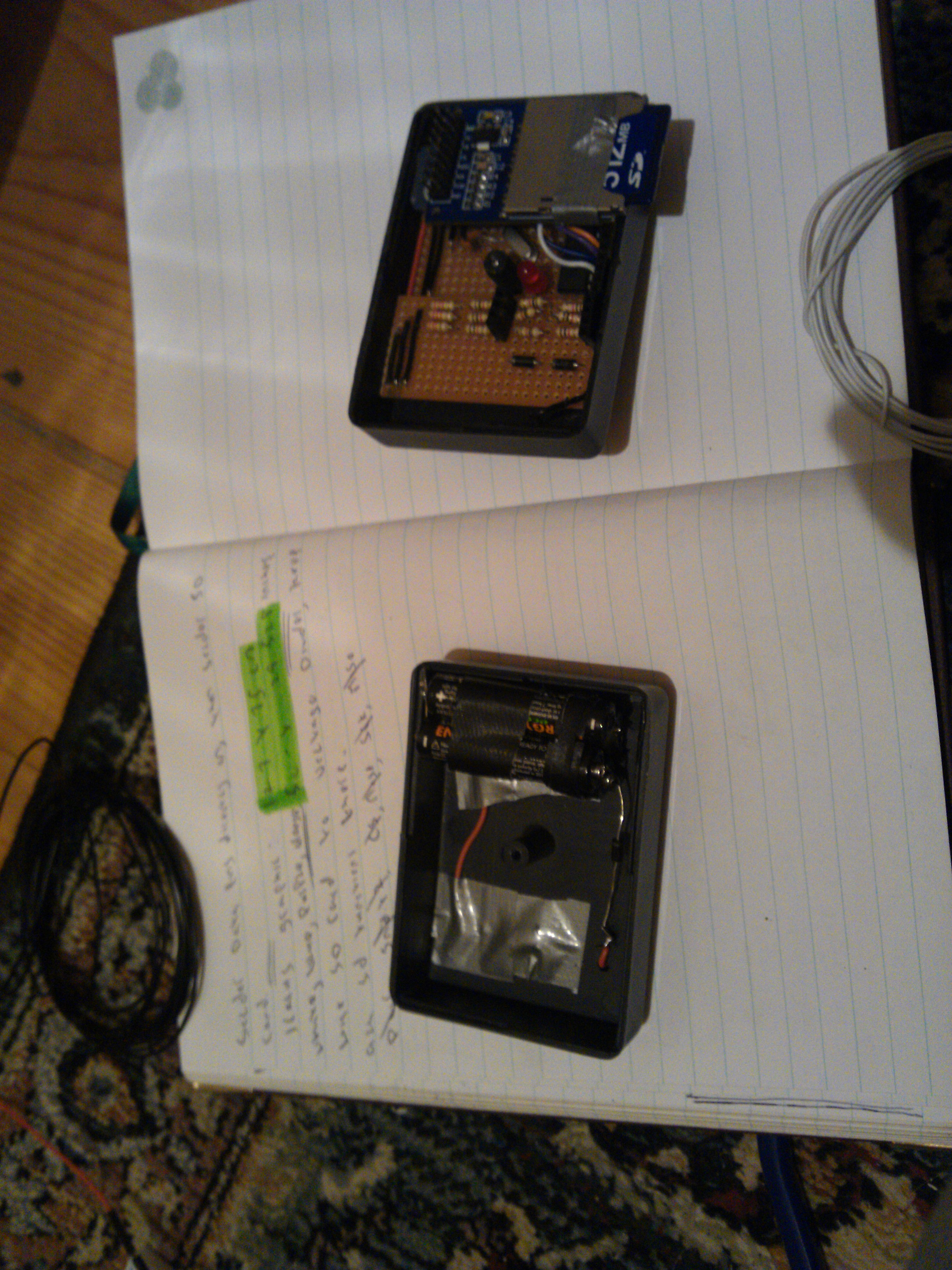
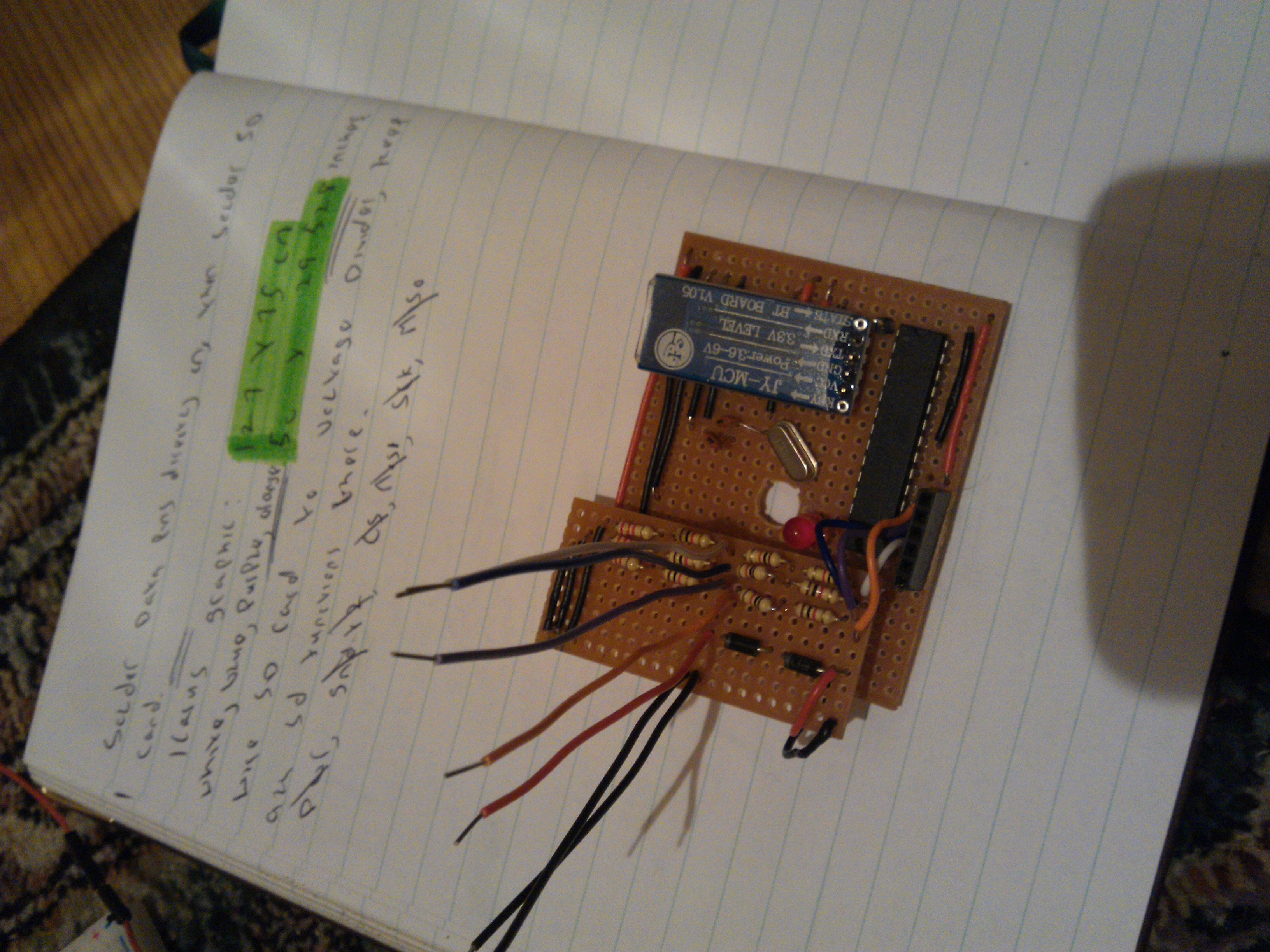
The board that I made fit exactly into the housing of the Datacache, which was perfect. I connected the voltage divider to the main project circuit board, leaving just enough room, hopefully, for the boost converter which has yet to be fitted.
The coloured wires on the voltage divider are the SCK< MISO, MOSI, and Chip Select wires going from the Arduino (at 5V) to the divider, and then being converted to 3.3v using the divider. The SD card reader will then be connected to the longer wires. The orange wire is not connected to any resistors, since this is the MISO wire, and, as the diagram shows, it does not need a divider.
This is a very useful and easy to build circuit, so I thought it was worth it's own post.